Question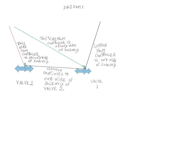 rainbird
QUESTION: hello!
1, is the attached wiring diagram correct for two valves
2. across which points should i measure voltage or ohms to ensure that the wiring system including solenoids are OK
3. what are the values for acceptance and rejection
4. if rejected what IS THE MOST LIKELY REASON AND WHAT IS THE REMEDY
5. AT THE CONTROLLER ESP-6 connections i want to measure the voltages but the wiring is such that it is very difficult to touch the multi meter prong with the metallic wires what to do
thank you do you accept donations
ANSWER: Hey Aamir, #1 yes the diagram looks correct, one common wire to both solenoids, and 1 hot wire to each solenoid #2 For ohms (resistance) or voltage (power) you can either check the wires at the controller, or at the solenoid. First thing to do, is turn on the power to the valve (solenoid) that you want to check. Then first touch the prongs from the volt/ohm meter at the controller, the negative prong to the common wire (C), and the positive prong to the hot wire (numbered terminal). you mention on question #5 that it is hard to touch the wire, I would disconnect the wire, and strip a little more insulation off of it, hook it back up, and this should make it easier to get to. Your reading (voltage) should be about 22 to 26 volts. If you are not getting a good reading, then you probably have a defective controller. If you are getting a good reading at the controller, then go out to the valve solenoid, and check the wires where they are hooked to the solenoid. Again, you should get between 22 to 26 volts. If you are not getting a good reading, but you are getting a good reading at the controller, then the wire is probably cut or damaged somewhere. You can do the same thing for your resistance reading, except you want to make sure there is no power going to the valve. Best thing to do, is actually disconnect the power to the controller. This time you need to disconnect the common wire from the controller, and the hot wire from the controller going out to the valve you want to check. Your ohm reading should be somewhere between 20 to 60 ohms. If it is under 20 ohms, then you have a short in the system, if it is over 60 ohms, then you have an open circuit. You can also go out to the valve, and disconnect the wires from the solenoid, and just check the wires going to the solenoid, and see what reading you are getting, again should be between 20 to 60 ohms. If you have a good resistance reading at the solenoid, but not at the controller, then you have a problem with the wiring. Normally if the solenoid is not opening, then it is either the controller, wiring, or solenoid, and these steps should enable you to pinpoint what it is. I hope this answers your questions, let me know if I can be of more assistance, thanks and have a great day.
---------- FOLLOW-UP ----------
 controller
QUESTION: thank you for a very good answer
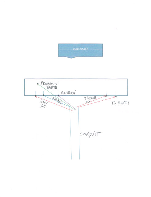
1. no voltage reading between common and any of two hot wires. i kept black prong to hot wire and left prong to common wire
2 similarly no voltage on the left red blue and green 24 V DC
3. there is power at wall outlet to which transformer i
4. the outside solenoid wiring is like the diagram earlier
note that this controller has been with us for over 6 years and has not given too many problems i think we should keep replacing controller as a last resort
is there a reset button or similar that can help here
AnswerHey Aamir, I did not realize that you were not getting a display on the screen. On #2 you say there is no power coming from the transformer (no voltage). Your problem sounds like the transformer is not working and needs to be replaced. Good luck and have a great day.